
The Bernard&Anne Spitzer
School of Architecture
SSA Robotics Lab
Cutter EOAT
Javier Álvarez Urrutia, Álvaro Ruiz de la Roja
Our mission was to find an End of Arm Tooling (EOAT) for our robot that would serve as a generic tool. This opened up a wide range of possibilities, since the task to be carried out was not specific. We could face this problem in different ways, either designing a single tool with which to perform multiple tasks (more complicated process) or designing multiple EOATs that could perform different tasks (simpler process), we finally decided to follow the latter.
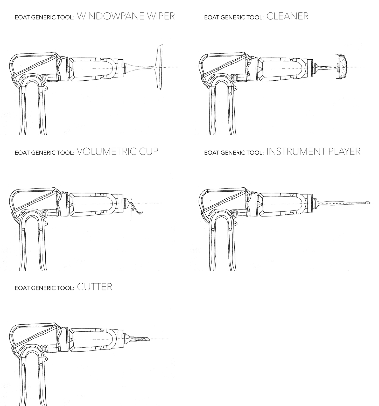
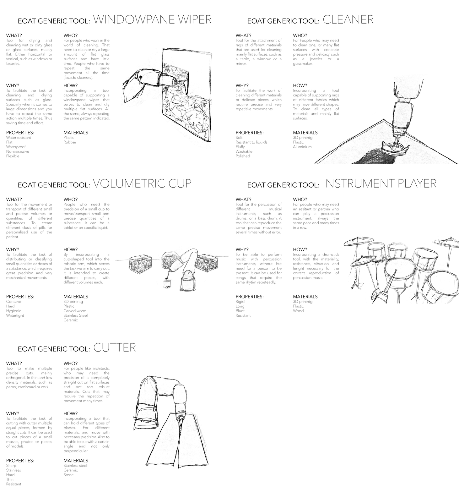
We came up with 5 different tasks that we could do with our EOAT: window wiper, polisher, volumetric cup, instrument player and cutter. Each one served a different purpose, whether it was cleaning a glass surface, playing a percussion instrument, or cutting paper or cardboard. Now we were faced with a second dilemma, to continue evolving each of the tools or to focus on one and develop it deeply. We decided to focus on one and saw that the one that offered us the most opportunities and seemed most interesting to us was the cutting function.
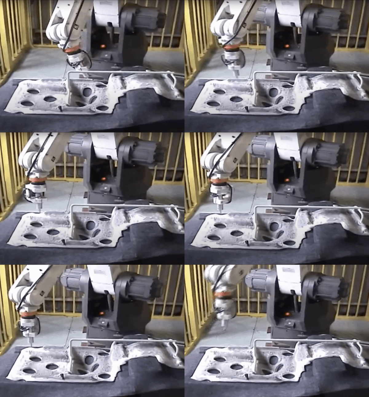

We studied references such as the one seen above from "Robotworx". Robotic cutting is the automated process of removing material from a work piece or dividing the work piece into several smaller, distinct parts. Cutting robots are extremely precise and accurate, while increasing speed. Decreased cutting errors reduces product waste. Depending on the product material, type of cut you wish to apply, will help determine the type of blade or cutter needed. Choose from a variety of customized or pre-engineered cutters to attach at the end of the robot arm. Cutting robot systems also help keep employees safe from dust or fumes that can occur during a cutting application.
REFERENCE: https://www.robots.com/applications/robotic-cutting


The objective was to design a piece that could grasp a blade so that it could cut a simple material such as paper or cardboard. The idea that first came up was to design a piece that would work like a clamp at the end of which would be the blade. Once we were clear about how the mechanism should work, we began to design our EOAT and establish the characteristics it should have.


The base must be the same design as the protective part of the robot, so that our EOAT can be perfectly attached to the robotic arm. The piece is shaped like a prism at the end of which it is divided into two “plates” that make the clamp work. Both are crossed by two holes that serve to insert the screws that adjust the pressure applied on the blade. In turn, the piece has a channel in the center that serves so that it can accommodate blades of different lengths, also crossed by a screw that holds the blade in place. To achieve a better grip and to prevent the blade from sliding, two rubber sheets are placed at the end what increases friction and prevents the blade from moving.


We printed a model of our EOAT in 3D and proceeded to examine it and test its operation. In the first design, the piece had a prismatic shape, but when it was time to tighten the screws at the end to make the clamp effect, the excess of material and stiffness added excessive tension to the piece, which was at risk of breaking. We also realized that in order to accommodate smaller, more accurate blades, we had to reduce the size of the through holes.
As a final result we have a piece with smaller through holes and with a curved end termination, which gives you flexibility in grasping the blade without risk of breakage.

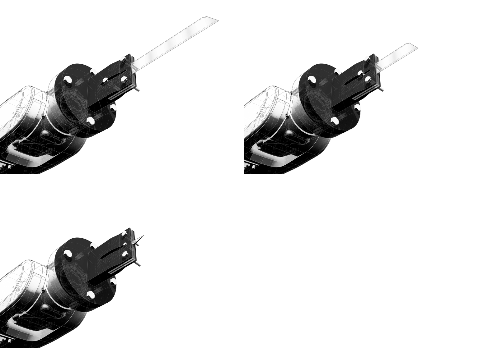
The design of our EOAT provides us with simplicity as well as versatility. It does not require overly complex or precise parts for its operation since with a few simple screws, nuts, washers and a blade it works. The versatility is given by the possibility of attaching different blades, from a cutter to a precision blade, thanks to the design and shape of the piece.

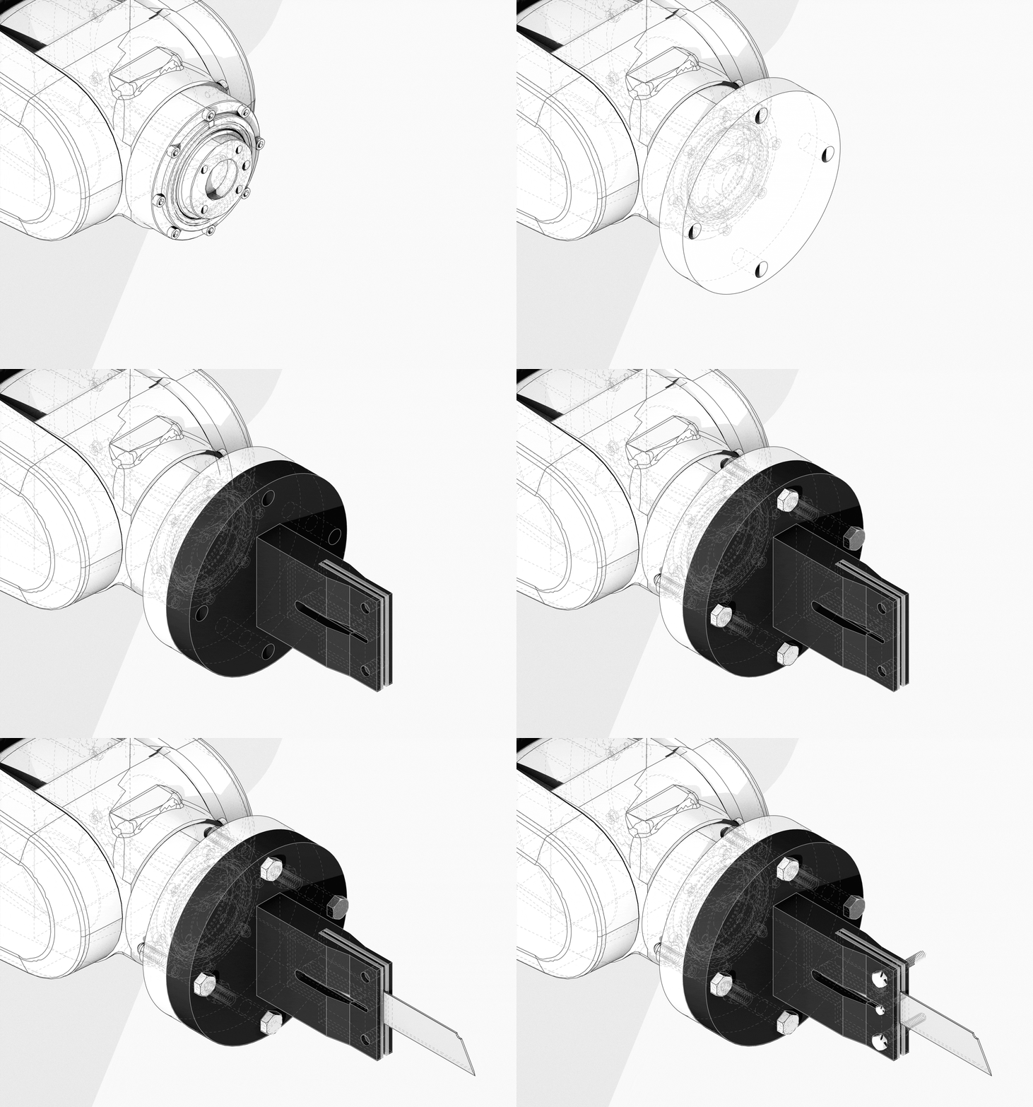
A protective base must be placed first, to avoid damaging the robotic arm. Our piece is attached to the base on the robotic arm through four 35mm-long screws. The desired blade is inserted between the rubber sheets, the first screw is placed according to the length of the blade and finally the two screws at the end of the piece are tightened until sufficient pressure is achieved.
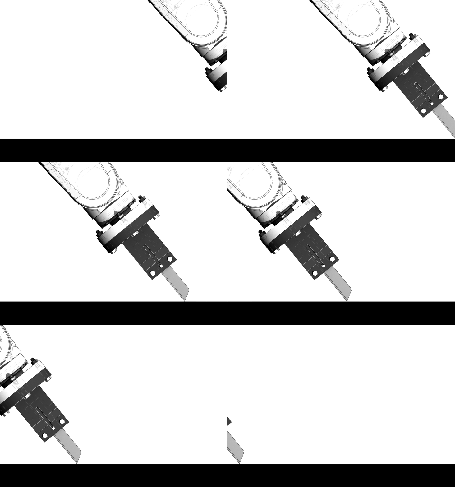
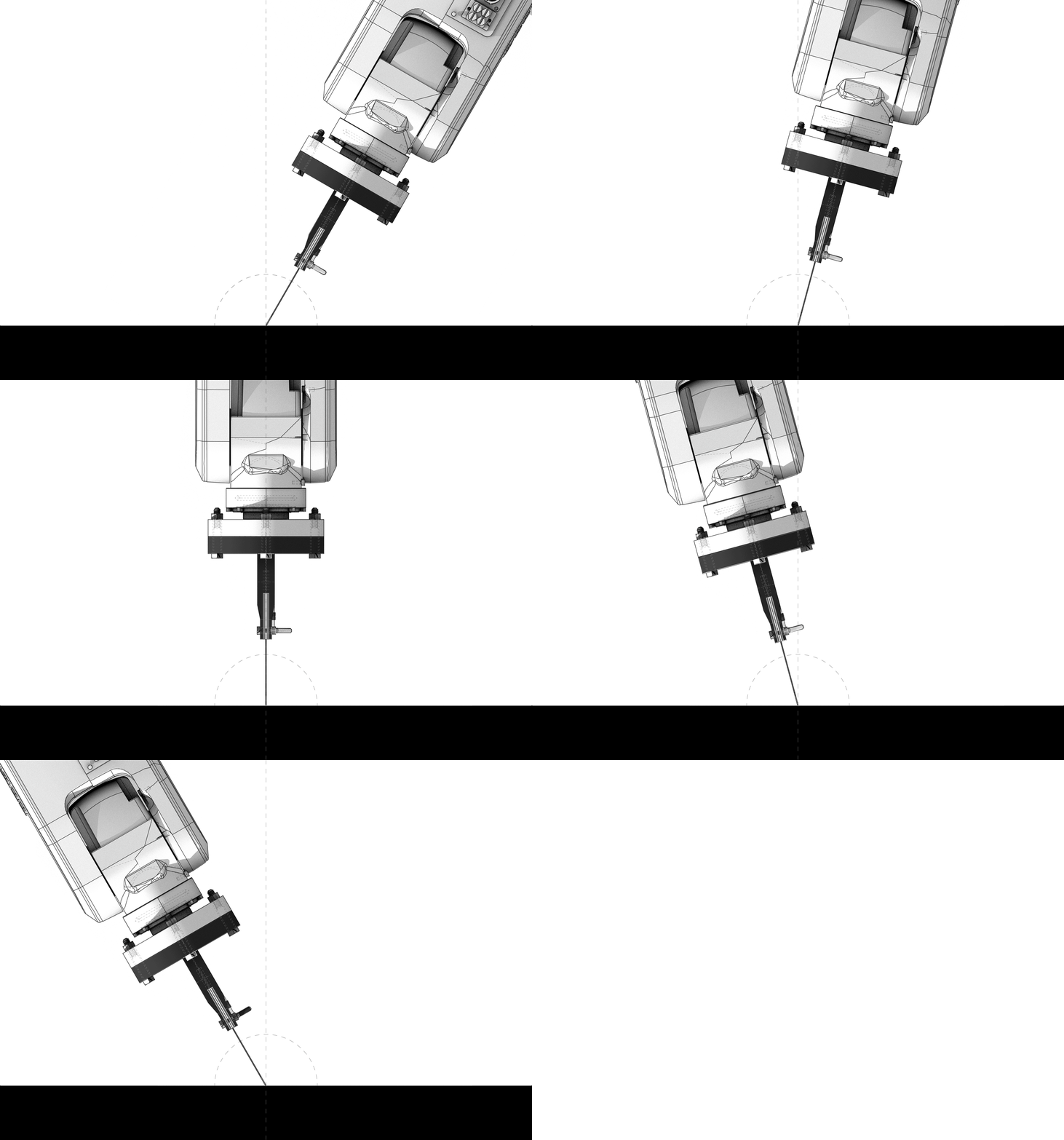
Once the robot is in operation, the objective is to be able to cut different shapes and sizes of pieces in 2D, always within the physical limits of the robot itself. In this case, due to the strength, size, and level of control of our robot, we could only cut materials such as paper or thin cardboard. The possibility of having a 6-axis robot allows us to cut the elements at a certain angle, which can be useful with thicker materials.


The way to make the robotic arm work is through the “Robot Studio” program. Initially we work with "Rhino" and its "Grasshopper" plug-in that facilitate understanding and control over the robot and later we go through "Robot Studio" that does a complete simulation of the process.
The way the robot works is by giving it a curve to follow, the program divides that curve into different points that create the path and the orientation to be followed by the robot. We can choose different speeds and shapes so that the robotic arm follows the curve and even program it to repeat the movement as many times as we want.
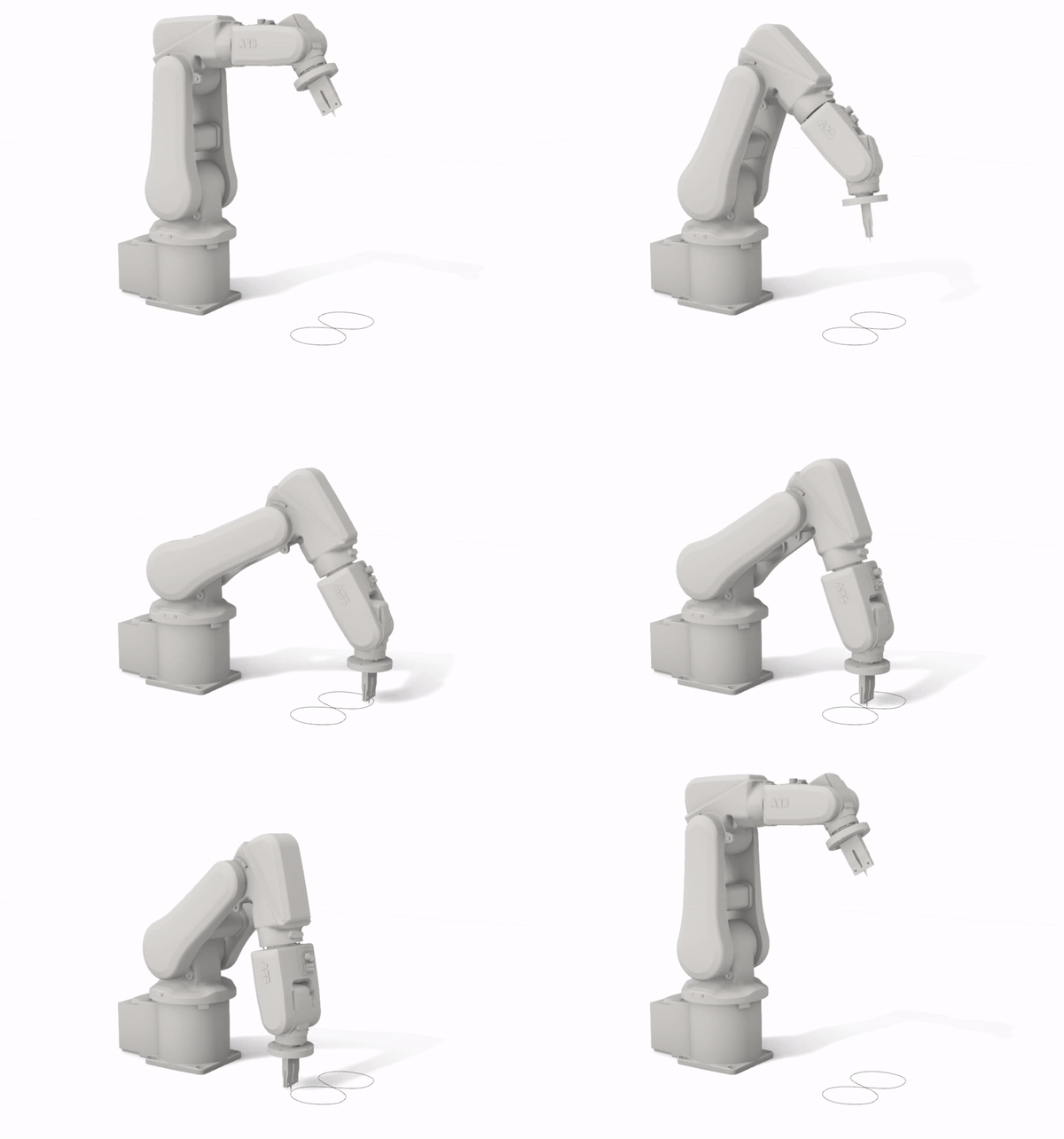
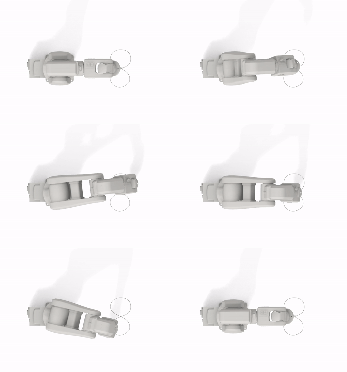
The final result that we obtain is an EOAT that serves to fit our robotic arm and allows us to cut different parts with precision and different angles. Probably the next thing to improve with this tool would be curved cuts or cuts with more pronounced angles, it will be necessary to continue investigating…